
AWARE
Summer of 2026
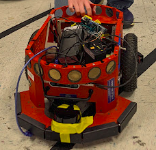
AWARE was an over 20 year old Pioner 3-DX Robot that was refitted with modern equipment. This Robot was inteded for agricultural robot research. I developed software allowing this robot to accomplish autonomous obstacle avoidance while pathing towards its goal.
This project was assigned to me during my CLAEM Internship at NC A&T.
Below is a button that leads to a youtube video of me presenting the project.Click HerePlease see the notable features below:Electronics and Communication
This project uses a Jetson Nano and an Arduino to control the robot. The Jetson Nano acts as the brain and interprets sensor data from cameras, lidar, gps, etc, and controls the overall state of the robot. The Arduino recieves information from the Jetson Nano via Serial Port and then decides what to do with it. For example, the Jetson Nano may send a command that says LeftDriveMotor,1 which tells the Arduino to set the left drive motor power to 100%.
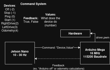 Above shows a diagram of the robots communication system between the Jetson Nano and Arduino.
To ensure the robot does not lose control when the Jetson Nano loses connection or crashes, the Arduino employs a heartbreat system where if the arduino does not receive a heartbeat (ping) from the Jetson Nano within a certain time (1.5 seconds), it will assume the Jetson Nano has lost connection and then stop all motor movements.
Wireless Control
To allow the user to control the robot wirelessly, I implemented a Wireless Interface using the Jetson Nano's built in wifi hotspot. I chose a hotspot because it allows the Jetson Nano to act as a standalone access point, rather than relying on an external router, meaning it could run anywhere in the world, especially important in an agricultural environment. I chose to have the Jetson Nano run Python because it has many libraries I planned to implement and one of these was FastAPI. FastAPI allowed me to make the robot host a server via uvicorn and connect it to a react front-end via websockets.
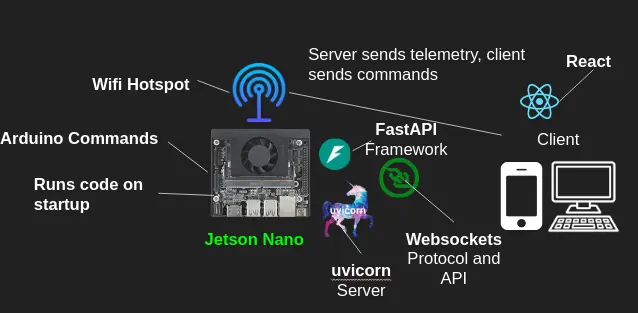 Above shows a diagram of the Robot Wireless Communication System
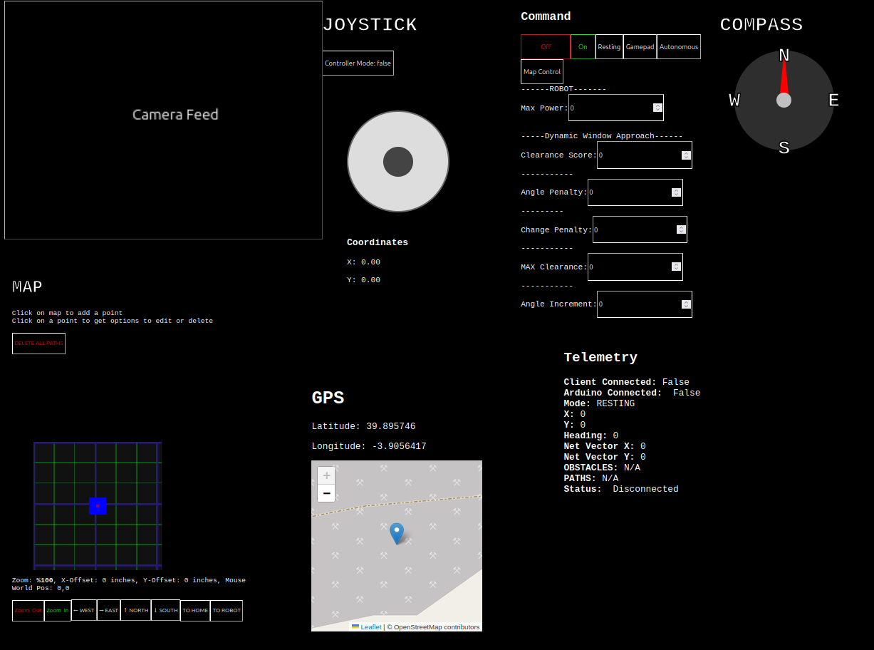 Above shows the interface. The user simply puts in the robots ip address into search bar and connects to the robot's wifi.
In this interface the user can see out of the camera (allowing for FPV control), change variables (useful for me especially for tuning variables), give the robot commands, control the robot via a joystick (either gamepad or thumbpad), see the robots compass direction, see the robots position on a local map at various zoom levels, see the robots position on a global map, and finally see the robots telemetry output.
Above shows a video of the robot being remotely operated in FPV.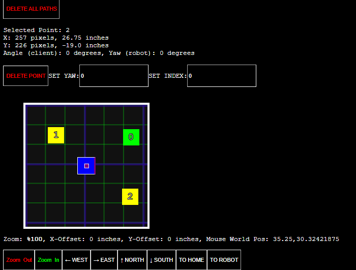 Above shows the mapping part of the interface where the user has selected multiple points for the robot to go to.
Sensors
Intel Real Sense D435i
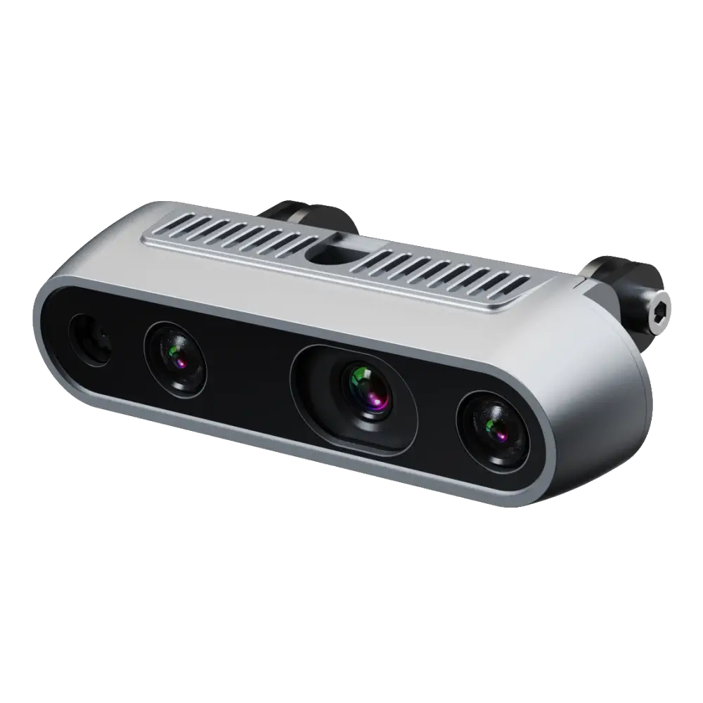 This Camera is stereoscopic and can measure depth. Additionally, it has an IMU built inside of it.
Wheel Encoders
 To measure positional and rotational displacement, the robot uses wheel encoder based odometry.
simpleRTK2b Budget GPS Module + GNSS Attenna
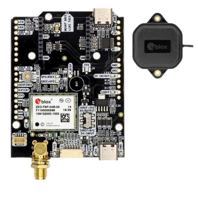 The robot uses RTK GPS to get a global reading on the robot's position, speed over ground, and course over ground.
RPLidar S2
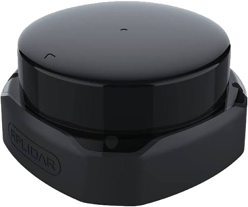 To percieve obstacles around the robot, the robot uses an RPLidar S2 2D lidar sensor.
Localization
Dead Reckoning
For dead reckoning, I combined IMU and Wheel Encoder odometry to estimate the robots position and heading via a kalman filter. However, this was still not enough as the robot's position, especially when outdoors, would drift significantly.
Global Localization
The robot needed global localization to correct for drift and to ensure accurate positioning.
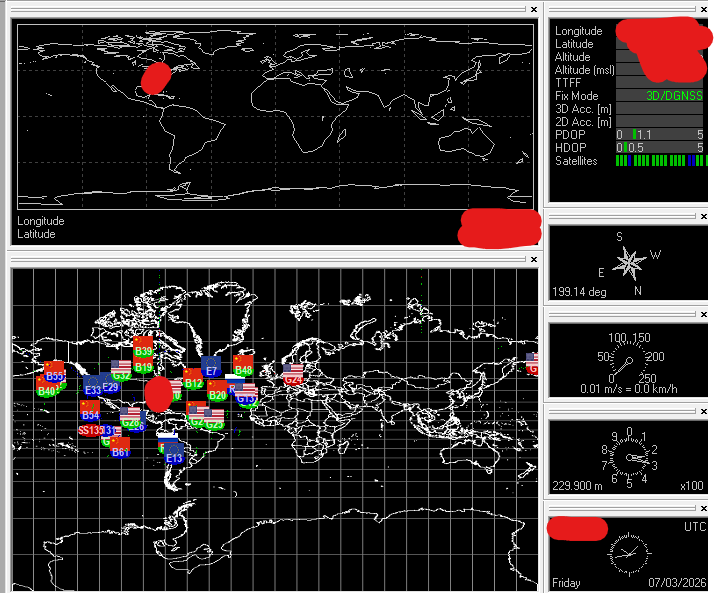 Above shows the u-center software running with a GPS connected.
While traditional GPS is effective for cars, it is not accurate enough for a small robot like AWARE. Here is a sample I took using matplotlib to visualize the GPS noise.
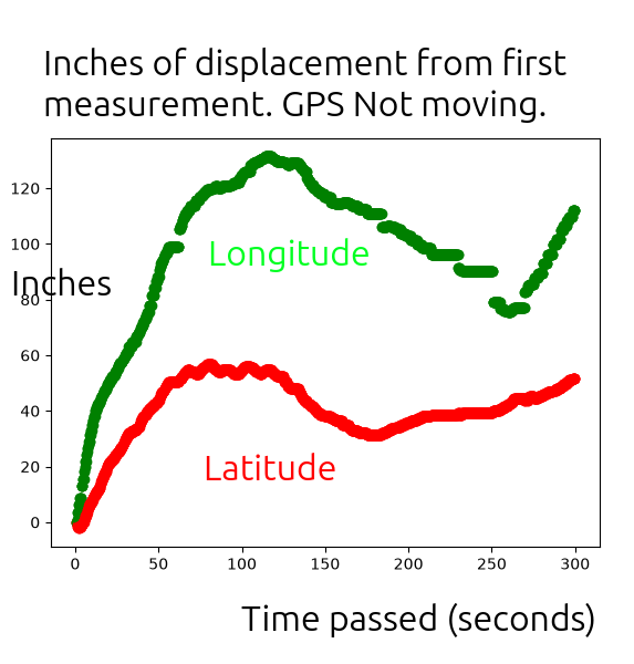 Above shows GPS displacement from its first reading while not moving over 5 minutes, showing that traditional GPS noisiness is over 100 inches, which is not accurate enough for AWARE.
RTK GPS
RTK (Real Time Kinematics) GPS requires a GPS on a base station (stationary) and the robot (rover). They connect to the same 4 satellites. Given enough survey time, the base station figures out exactly where it is and can calculate the “error” of the given gps readings. Then it sends the error information to the rover, which it uses to remove the error from its gps reading, leading to a much more accurate reading
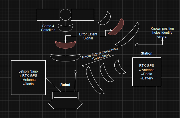 Above shows the RTK GPS setup, with the base station (stationary) and the robot (rover) connected to the same 4 satellites.
To effectively transmit the RTK corrections to the robot, I used a SiK Telemetry Radio to send the RTK data over the air, and then another radio on the robot to recieve this data and write the corrections to the robot's GPS module. I chose radio as opposed to using the robot's hotspot as the transmission medium, as radio provides a more reliable (no disconnecting), greater range (up to 2km) and direct connection (no need for wifi module on base station).
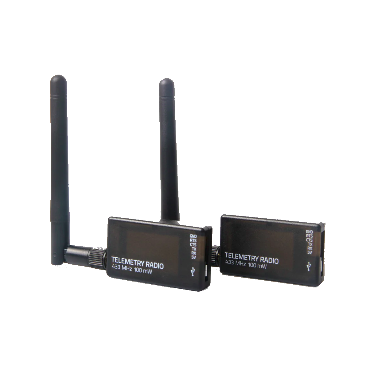 Above shows the two SiK telemtry radios.
 Above shows RTK GPS displacement from its first reading while not moving over 5 minutes, showing that RTK GPS is much more accurate than traditional GPS (within 10 inches).
RTK GPS readings alone suffer from lower frequnecy (1 - 10Hz) and are still noisier than the dead reckoning sensors, so to maximize effectiveness I had to combine both approaches, allowing for the robot to navigate more reliably and accurately.
Mapping
Even with perfect localization (which it is not), the robot still needs to map the environment to avoid colliding with obstacles. To do this I used two sensors: a LiDAR and a camera.
LiDAR
The lidar provides an extremely accurate baseline of the obstacles around the robot (over 3000 measurements with little noise). However, because it is 2D, it cannot see above or below where the Lidar is located.
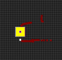 Above shows a map the lidar produced, where red blocks represent obstacles and the yellow block represents the robot.
Depth Camera
The Depth Camera provides a 3D view of the environment in front of the robot, then by finding the closest points on each column in view, the robot can generate a 2D top down view map of the closest obstacles. However, these measurements are much noisier, the range is limited, and the field of view is much smaller.
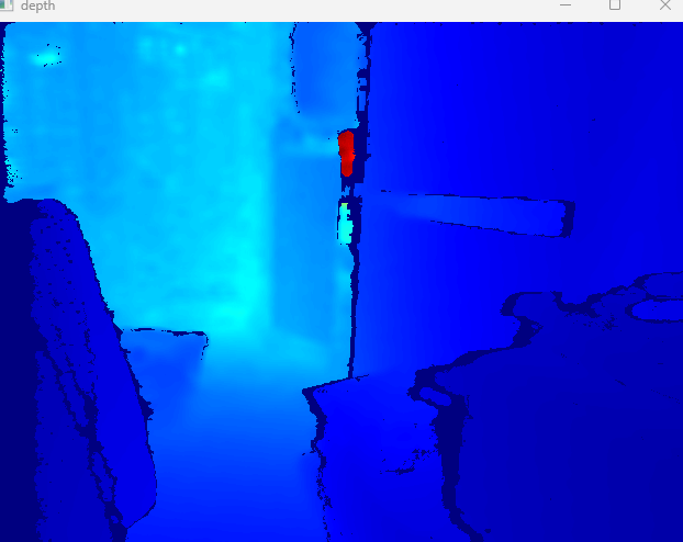 Above shows a 3D view of the environment as seen by the depth camera.
By combining both of these sensors, the robot has a more accurate view of the environment and can navigate more effectively.
Above shows the robot running obstacle avoidance while driving forward. This is purely perception, no object permanence and no target position, just driving forward avoiding collisions.Mapping pure perception is limited, in order to path around obstacles consistently, the map must remember where obstacles were. To achieve this I used a confidence based system where obstacles are saved onto a map at a certain confidence value, then as time passes the confidence decreases until eventually it is removed from the map. Obstacles that are theoretically visible based on the Camera's FOV have a greater confidence decay as if they aren't actually seen while they should be then it is more likely they are no longer there.
Obstacle Avoidance
Pathing
To navigate around the obstacles without colliding, the robot uses Dynamic Window Approach (DWA) to generate an angle and speed the robot should move at. It works by sampling a window of possible movements and selecting the one that minimizes a cost function, where greater changes in angle is a penalty and greater clearance to some degree is a reward.
Above shows a video of DWA in action.I originally tried A* pathfinding but it was too computationally expensive to run every frame. Then I tried using Artificial Potential Fields (APF) but this approach is better suited for aerial drones as on the ground it would easily get stuck at local minima. I finally decided to use DWA after talking to a graduate student about local path planning, where I was informed that the industry standard approach for ground robots is the Dynamic Window Approach.
Control
Based on the path generated by DWA, the robot uses a two PID controller system. Since the robot uses differential drive, the robot cannot simply, for example, drive left. Instead, the robot must turn first, then drive forward. To prevent the robot from constantly stopping to turn, I first created a PID controller for the robot's heading, then a second PID controller for the robot's forward motion that had a cosine relationship with the heading error (greater heading error means less drive control and vice versa).
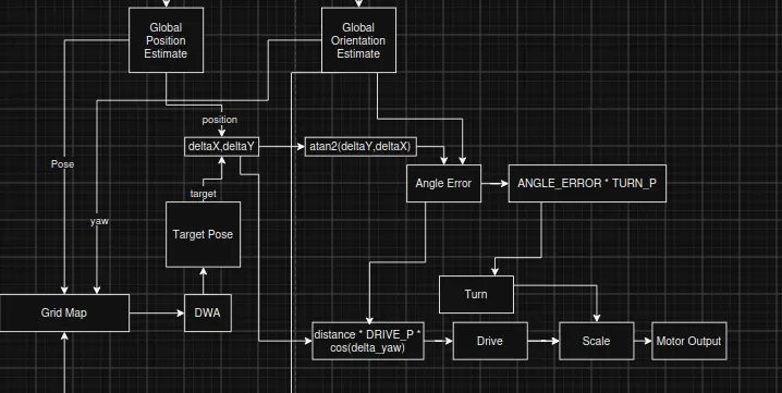 Above shows a diagram of the robot's control system.
Object Detection and Grabbing
I was fortunate enough to work with a robotic arm. For proof of concept I implemented the YOLO object detection algorithm and trained it on a custom dataset of cups. Then, I made the arm be able to pick the closest identifiable cup and extend out via inverse kinematics to grab to the cup. While this arm was never actually attached to aware, I was able to use it to show how, theoretically, aware could use an arm to identify and grab fruits, weeds, etc.
Below is a button that leads to a youtube video of me demonstrating the arm cup grabbing logic.Click Here